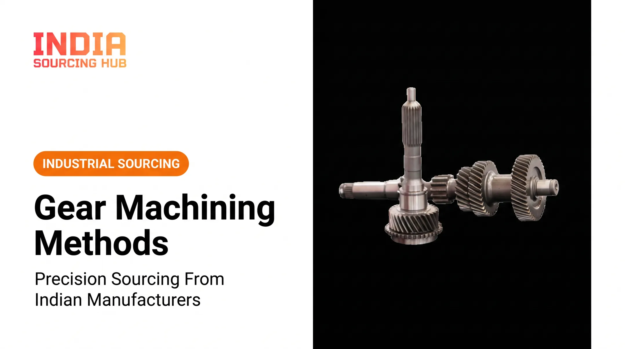

This guide is written for US-based engineers, OEM buyers, procurement teams, and manufacturers specifying gears for industrial machinery, automotive and truck components, pumps, valves, robotics, and transmission systems. Tooth accuracy, repeatability, and material control directly affect noise, load transfer, wear, and service life.
You'll find a breakdown of gear types, machining methods, the end-to-end workflow, accuracy factors, supplier-selection criteria, and situations where a different manufacturing route makes more sense.
Key Takeaways
- Match the cutting process to geometry, material, volume, accuracy, and operating speed—gear cutting is only one stage
- Assign hobbing, shaping, skiving, milling, broaching, grinding, honing, or lapping by the role each plays in the workflow
- Control blank concentricity, heat-treatment planning, and specialized inspection to lock in real-world performance
- Evaluate suppliers on technical capability, documentation, and delivery reliability, not just unit price
What Are CNC Gears and Why Is CNC Machining Used?
A "CNC gear" is simply a toothed component produced with computer-controlled equipment. CNC describes the machine control, not a single production method. The same label covers hobbed spur gears, skived helical gears, and ground bevel pinions.
CNC gear production delivers:
- Accurate tooth count and spacing for predictable meshing
- Controlled backlash and contact pattern
- Appropriate surface condition for the application
- Repeatable power or motion transmission, run after run
Cutting generates the teeth, but machining is the whole job. Gear machining also includes turning the blank, boring, cutting keyways, planning for heat-treatment growth, finishing, deburring, and inspection. A quote for "cut teeth" alone doesn't guarantee any of that scope is included.
Choosing the right process starts with matching it to the part. CNC equipment fits custom, prototype, low-to-medium-volume, and technically demanding gears particularly well. Gleason's CNC bevel-gear platforms, for example, are built around repeatable production and shorter changeovers, with Gleason's Phoenix 1000HC bevel-gear cutting system supporting flexible program creation for large bevel gears. That's a machine-specific advantage, not proof that CNC always beats manual cutting.
Manual or less-specialized cutting can still work for simple, low-criticality parts, but operator-dependent setups introduce variation between batches. When consistent tooth geometry matters across hundreds or thousands of parts, that variation becomes a liability.
How CNC Gear Cutting Works: From Blank to Finished Gear
The path from drawing to finished part follows a consistent sequence: review the design, prepare the blank, generate the teeth, apply heat treatment where specified, finish, then inspect before packaging.

Step 1: Review the Design and Prepare the Blank
Before any cutting starts, confirm:
- Gear type, module or diametral pitch, tooth count, pressure angle
- Helix or cone angle, face width, bore, and keyway
- Mating gear specifications and material
- Quantity, tolerance class, operating speed, load, lubrication, and environment
Skipping this review is where a lot of rework starts. Turning operations then establish the blank's outside diameter, faces, bore, and datum surfaces.
Runout introduced here carries straight through to final tooth engagement. A blank that's off-center going in won't mesh correctly coming out, no matter how precise the tooth-cutting operation is.
Step 2: Generate the Gear Teeth
Synchronized tool and workpiece motion cuts the tooth profile into the blank. The process you choose — hobbing, shaping, skiving, milling, or broaching — depends on gear geometry and production volume.
Here's the part buyers often miss: the first tooth-cutting pass typically establishes basic profile and spacing. It doesn't necessarily deliver the final accuracy, surface finish, or hardened condition the application needs. That comes later.
Step 3: Treat, Finish, and Verify the Gear
Carburizing, nitriding, induction hardening, or through-hardening may follow tooth generation, depending on the material and load requirements. Research how your specific material responds to heat treatment rather than assuming a universal sequence applies.
Post-treatment finishing options include:
- Grinding — corrects profile, lead, and distortion from hardening
- Honing or lapping — refines surface finish and reduces noise
- Shaving, chamfering, deburring — cleans up edges and removes burrs before assembly
Final inspection typically checks:
- Profile, lead, pitch, and runout
- Bore concentricity and tooth thickness
- Surface finish, hardness, and contact pattern
This is where specialized gear-measuring equipment matters. Gleason's in-process gear inspection systems combine laser-based tooth measurement with double-flank rolling tests to capture profile, lead, pitch, and runout together.
A general-purpose CMM, without gear-specific software and probing, won't reliably catch the same issues.
CNC Gear-Cutting Methods, Applications, and Selection
No single cutting method works for every gear. Geometry, access, volume, and finishing requirements all narrow the field.
| Method | Best suited for | Role |
|---|---|---|
| Hobbing | Accessible external spur and helical gears | Roughing or finishing |
| Shaping | Internal gears, shoulder-restricted designs | Primary cutting |
| Power skiving | Internal and external cylindrical gears, suitable machine rigidity | Primary cutting |
| CNC milling | Prototypes, low volumes, bevel/helical features, tough materials | Primary cutting |
| Broaching | High-volume internal forms and splines | Primary cutting |
| Grinding | Hardened gears needing tight profile/lead control | Finishing |
| Honing | Hardened transmission gears | Finishing |
| Lapping | Mated bevel and hypoid gear pairs | Finishing |
Hobbing generates teeth through synchronized rotation of a hob cutter and the blank. It remains the default for external cylindrical gears, but it can't reach internal teeth or geometry with restricted tool access.
Shaping covers internal gears and shoulder-restricted designs where a hob simply can't fit. Power skiving can run faster than shaping when the machine has the rigidity and synchronization for it, and it scales well for medium-to-large batch cylindrical work.
CNC milling fits prototypes, one-offs, unusual profiles, and tough materials when dedicated tooling isn't justified. Broaching sits at the other end of the volume spectrum: dedicated tooling only pays off on repeatable, high-volume internal forms such as splines.
Grinding, honing, and lapping are refinement steps, not primary cutting methods. After heat treatment shifts dimensions, they restore profile accuracy, surface finish, and noise behavior on hardened gears.

Gear Types and Common Applications
- Spur — parallel shafts, direct torque transfer
- Helical — parallel shafts, quieter than spur gears
- Bevel — intersecting shafts, common in differentials
- Worm — high reduction ratios; efficiency vs. noise trade-off
- Internal — compact layouts and high-reduction gearboxes
- Rack-and-pinion — converts rotation into linear motion
- Splines — torque-transmitting fits in hubs and planetary carriers
Supplier and Sourcing Checkpoint
Before awarding a gear job, ask the supplier for:
- Comparable gear production experience for your geometry and material
- Cutting and finishing capability matched to your accuracy requirements
- Gear-specific inspection reports, not just a CMM printout
- Material and heat-treatment traceability documentation
- Sample approval procedures and production process controls
- Clear lead-time planning and corrective-action processes
India Sourcing Hub connects North American buyers to a vetted Indian factory network for gear work. The team coordinates quality requirements, import logistics, and inventory warehousing in Chicago and Toronto, so you aren't managing overseas vendors alone.
Accuracy Factors, Common Issues, and Misconceptions
Gear accuracy comes down to a handful of measurable characteristics, each tied to a real performance outcome.
| Geometry control | Affects |
|---|---|
| Profile deviation | Load distribution across the tooth |
| Lead deviation | Contact pattern across face width |
| Pitch or spacing error | Vibration and noise |
| Radial runout | Mesh consistency, backlash variation |
| Tooth thickness | Backlash, fit with mating gear |
| Bore concentricity | Alignment, assembly performance |
Machine and process factors compound these controls. Spindle and axis synchronization, fixture datum strategy, tool condition, thermal growth, and coolant management all influence whether the cut teeth match the drawing. In-process verification catches drift before it reaches the finishing stage.
Material and heat treatment introduce further risk. Machinability changes before and after hardening. Quenching can introduce nonuniform stresses that change flatness, roundness, and tooth geometry. Gear Solutions reports that controlled press quenching helps manage this distortion, though it doesn't eliminate it entirely.
That's why finishing allowance needs to be planned before hardening, not after.

Common Misconceptions
- CNC milling isn't automatically the best method for every gear
- Gear cutting isn't the same as complete gear machining
- Passing basic dimensional inspection still fails if profile, lead, runout, or contact pattern stay uncontrolled
- Tighter tolerances shouldn't be specified without a functional reason behind them
Practical Quality-Control Checklist
- Drawing review and material certificates on file
- First-article inspection before full production
- Process capability evidence and defined sampling frequency
- Heat-treatment records tied to each production lot
- Final gear measurement plus mating-gear checks
- Nonconformance handling and full traceability
Standards to Confirm on the Drawing
ISO 1328-1:2013 and ISO 1328-2:2020 govern cylindrical-gear flank tolerance classification and radial composite deviations, respectively. Some older AGMA accuracy documents are now historical or inactive. Confirm the exact document and edition on your drawing; don't mix grading systems without a documented comparison.
When CNC Gear Machining May Not Be Appropriate
Precision CNC gear machining isn't always the right call. For standardized, high-volume gears with stable geometry, dedicated hobbing, forging followed by finishing, powder metallurgy, or stamping can be more economical.
Precision CNC machining may be overkill when:
- Load and speed are low and the mechanism isn't critical to safety or uptime
- Basic dimensional accuracy and functional fit are genuinely all that's needed
- The design doesn't offer practical datums or finishing allowance to begin with
Watch for these constraint signals too:
- Extremely high volume that justifies dedicated tooling instead
- Inaccessible internal geometry or unusually hard materials
- Insufficient inspection capability to document tooth quality
- A supplier quoting the job without asking about load, speed, mating gears, or service life
Alternative routes have their own limits. A forged blank reduces machining steps but still requires finish machining afterward.
Fineblanking can also remove process steps, but a 2023 study in the International Journal of Advanced Manufacturing Technology found load-capacity limitations in commonly used shear-cut steels compared with case-hardened gears. Fewer manufacturing steps don't automatically mean equivalent performance.
Reassess your process if you're seeing:
- Repeated tool changes
- Excessive scrap
- Unplanned post-treatment correction
- Inability to document tooth quality on request
Process selection should balance performance, total cost, tooling investment, lead time, and supply-chain resilience — not whichever method sounds most advanced.
Conclusion
CNC gear manufacturing is a coordinated chain: design review, blank preparation, tooth generation, treatment, finishing, and specialized inspection. The right route depends on gear type, material, volume, accuracy requirements, and operating conditions — there's no universal answer.
US buyers need to weigh technical capability and supplier-management reliability:
- Documentation and quality controls
- Clear communication and delivery planning
- Ability to manage overseas sourcing risk
India Sourcing Hub has coordinated metal-product sourcing for North American manufacturers since 1995. Its Indian factory network has been vetted to North American quality standards since 2013, with technical support through production, warehousing in Chicago and Toronto, and manufacturing support in Rajkot.
If you have gear drawings, specifications, or sourcing requirements to work through, India Sourcing Hub can help identify qualified suppliers and coordinate quality and logistics from sample approval to delivery.
Frequently Asked Questions
What are the different types of gears?
Common types include spur, helical, bevel, worm, rack-and-pinion, internal, and splines. Selection depends on shaft arrangement, load, speed, noise tolerance, and whether motion needs to change direction.
How are gears machined?
The process starts with blank preparation, then tooth generation using hobbing, shaping, skiving, milling, or broaching. Heat treatment, grinding or honing, deburring, and inspection follow when the application requires them.
Which CNC gear-cutting method is best for a custom gear?
No single method fits every job. Choose based on internal vs. external teeth, material, quantity, accuracy, available equipment, and finishing needs.
When is gear grinding required after cutting?
Grinding is typically required for hardened gears, after heat-treatment distortion, or when profile, lead, noise, or high-speed requirements exceed what cutting alone can deliver.
What information is needed to source or manufacture a custom CNC gear?
Suppliers need drawings or CAD files, gear type and tooth data, material and heat-treatment specs, quantity, and tolerances. Mating-gear details, operating conditions, finish requirements, and delivery expectations complete the package.